# Innovative Approaches to Developing a Copper-Based Electrolytic Memristor
Written on
Chapter 1: Introduction to Electrolytic Memristors
In this segment, I delve into my third experiment focused on developing what I term an "electrolytic memristor." This device functions similarly to an electrochemical cell, essentially acting as a resistor. The unique aspect of this setup is that the voltage applied across the cell prompts a metal, like aluminum or copper, to deposit onto the electrode's surface from the electrolyte, thereby modifying its resistance.
For foundational theory, refer to my initial article: "An Experimental Open-Source Memristor/Programmable 'Diode'." Further insights into potential neural networking applications can be found in my second piece, "The Crafted Mind: Building an Electrolytic Memristor Neural Network, Part 2."
My earlier investigations revolved around the challenge of plating aluminum in a deep eutectic solvent (DES), which proved quite complex in my home lab. However, I realized that copper is particularly adept at plating. A significant hurdle I faced was locating a consistent resistive ribbon; many options I encountered had resistance levels too low for my intended effects. Recently, while reviewing some notes, I discovered I had produced a conductive (resistive) plastic by treating PETE (#1) sheets—the containers used for berries—with graphite powder. Initially, I aimed to utilize this for the light-accessible side of a dye-sensitized solar cell, but I concluded that the resistance was too high for that application.
Yet, last night, it dawned on me that I had stumbled upon the resistor I needed! While I can probably refine this approach further, it felt rewarding to finally test the concept.

Chapter 2: Plating Process and Results
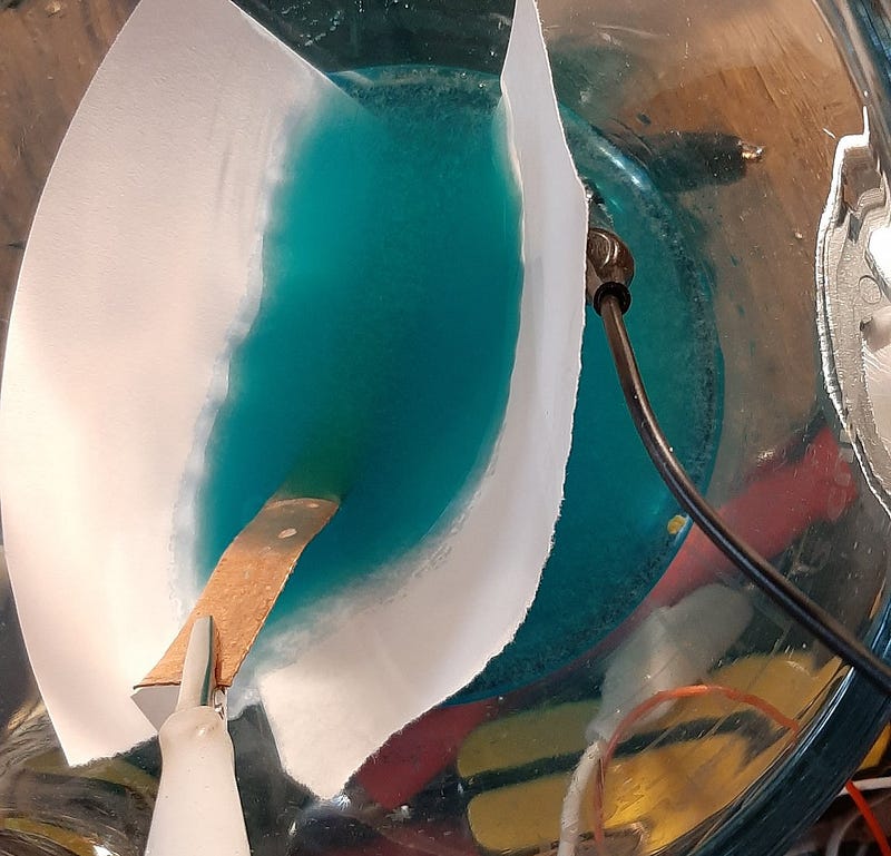
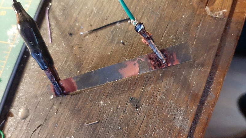
In my experiment, I utilized a solution of Copper Sulfate and Sodium Sulfate, employing a copper sheet as the substrate for plating on the graphite-PETE combination. Although I haven't yet characterized the cell thoroughly, the initial observations confirm that copper indeed plated onto the surface in the anticipated gradual manner characteristic of a memristor. This cell can be removed for use as a memristor, although it requires substantial voltage.
The copper produced is somewhat brittle, but measurements show that areas covered with copper exhibit a resistance of approximately 0.1 Ohms, while "open" regions maintain a resistance near 8 kOhms/cm. Although the plating process was slow, I believe that employing smaller sheets can enhance efficiency.

Chapter 3: Preparation and Operation
Preparation Steps:
- Rub graphite onto a PETE sheet (or blend graphite with a binder/epoxy to achieve the desired resistance).
- Prepare a plating solution combining Copper Sulfate and Sodium Sulfate.
- Attach two negative electrodes at either end of the memristor.
- Connect a positive lead to a sacrificial copper electrode.
- Apply a voltage of 2V (higher voltages can also be used) to facilitate copper plating near both terminals.
Operational Mechanics:
Once the memristor achieves a sufficient baseline resistance, it can be removed from the plating bath and placed in a smaller one. This ensures an even distribution of copper on each electrode.
As current flows through the resistor, copper migrates towards the negative terminal, increasing the overall resistance. When the current direction is reversed, copper returns to the original position, decreasing the resistance. Theoretically, with 1/3 of each end covered at 8 kOhms/cm (1 cm copper, 1 cm open, 1 cm copper), the midpoint resistance should be 8 kOhms. After current passes through the cell, resistance should rise to 16 kOhms, and only 1/3 will be plated. Reversing the current should allow it to settle back to 8 kOhms before potentially rising again to 16 kOhms.

Chapter 4: Future Ideas and Considerations
One intriguing concept involves using a sealed copper tube with isolated leads, allowing users to "unplate" the PETE onto the inner surface of the tube or replate as needed. Alternatively, one could encase the device in a paper soaked in a copper sulfate/sodium sulfate solution. Working voltages should ideally remain below 1.23V to prevent water splitting, with a DES potentially offering greater durability.
Another thought is to create access points within the 2D sheet arranged in a grid pattern to function as dendrites. Rather than just two terminals, envision a grid of 16, allowing each electrode to maintain distinct values. Additionally, the plastic sheet could enable another electrode on the opposite side to treat output signals as capacitive values, effectively summing data points. I'm uncertain how this configuration might influence the plating, similar to floating gate memristors found in flash RAM, but it's a fascinating direction to explore in the quest to construct a neuron from the ground up.